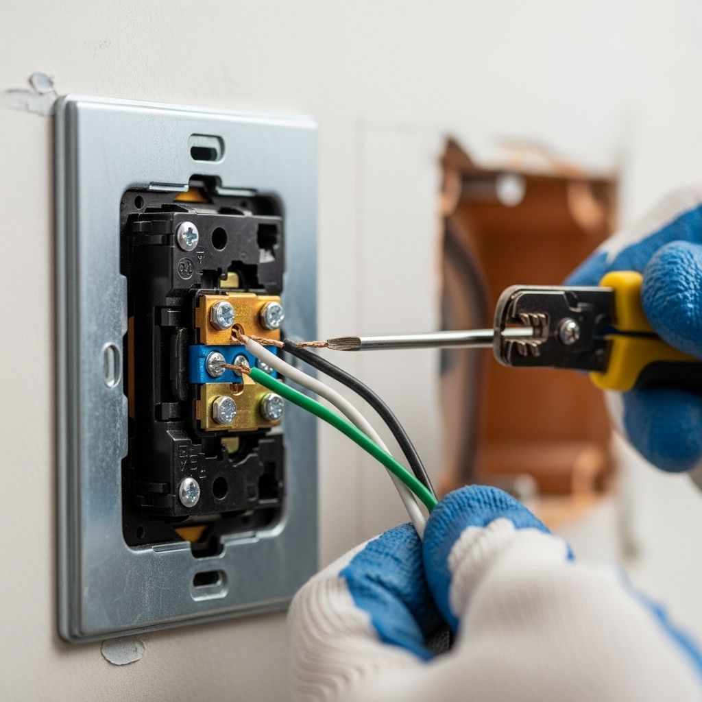
A Complete Guide to Electrical Switch Wiring: Techniques, Safety, and Troubleshooting
Master proven techniques for safe, efficient lighting control in every room.

Electrical Switch Wiring: An In-Depth Guide for Homeowners
Upgrading or repairing electrical light switches is a common home improvement project with significant safety and performance implications. This detailed guide explains proven methods for wiring switches, the differences between switch types, troubleshooting techniques, and essential safety precautions. Whether you’re installing a new single-pole switch or replacing an outdated device, mastering key wiring principles ensures reliable operation and minimizes risk.
Understanding Light Switch Basics
Light switches serve as the primary control point for lighting circuits throughout your home. They operate by interrupting or completing the electrical circuit to a fixture, thereby turning lights on or off. The most common types include:
- Single-pole switches: Control a single light or fixture from one location.
- Three-way switches: Allow control of a light from two separate locations (such as at the top and bottom of a staircase).
- Four-way switches: Used in conjunction with three-way switches to control lighting from three or more locations.
Correct identification and handling of wires is essential. In a typical residential switch setup, you’ll encounter:
- Hot (black or red): Carries current from the power source.
- Neutral (white): Carries current back to the panel.
- Ground (bare or green): Provides a safety path to the earth.
Basic Tools and Materials Needed
- Wire strippers
- Phillips and flathead screwdrivers
- Voltage tester
- Electrical tape
- Wire nuts or connectors
- Replacement switches
- Grounding screws or pigtail wires
Always ensure your workspace is dry and clear of any hazards before starting.
Safety Precautions When Wiring Switches
Electrical work presents serious risks. Adhering to these guidelines safeguards you and your home:
- Turn off power at the circuit breaker before beginning any wiring task.
- Test wires using a non-contact voltage tester to confirm power is off.
- Wear insulated gloves and use tools designed for electrical work.
- Follow local electrical codes and consult an inspector if unsure.
- Do not work alone. Have someone nearby in case of accidents.
Step-by-Step Wiring Methods for Single-Pole Switches
Single-pole switches are the simplest and most prevalent in homes. They typically feature two brass terminals (for the hot wires) and one green screw for grounding.
Method 1: Middle-of-Run Single-Pole Switch
In this configuration, the power source enters at the switch box and continues to the light fixture. The steps are as follows:
- All neutral (white) wires are twisted together and capped with a wire nut.
- The ground wires are joined and connected to the switch’s ground terminal.
- Both hot (black) wires are attached to the brass terminals on the switch—either terminal can be used for incoming or outgoing hot.
- Ensure no bare copper is exposed beyond the nut or terminal; secure all connections tightly.
- Restore power and test the switch.
Method 2: End-of-Run Single-Pole Switch
Here, the power enters the light fixture first, then continues to the switch. This setup uses the switch loop:
- At the light fixture, connect the incoming neutral wire to the fixture’s neutral terminal.
- Connect the ground wires together and to the fixture and switch, ensuring continuity.
- The black hot wire from the power source joins the white wire running to the switch (marked with black tape to indicate it carries current).
- At the switch, connect the white (marked) wire to one switch terminal; the black return wire to the other.
Label the white switch loop wire with black tape to ensure proper identification as a hot return.
Method 3: Multi-Wire Switch Loops (Using 3-Conductor Cable)
Some installations require a 14/3 cable (with black, red, white, and ground wires) for advanced switching options. Steps include:
- At the fixture, connect power and fixture neutrals together.
- Twist and cap all ground wires, joining to device grounds as needed.
- Black and red wires in the switch loop handle the hot and return; red wire may serve as a traveler or separate circuit.
- Wiring connections must follow the applicable code for identification and safety.
Common Mistakes and How to Avoid Them
Errors during switch wiring can lead to poor performance, risk of electric shock, or even fire. Avoid these frequent mistakes:
- Not stripping enough wire insulation: Prevents good contact and may cause arcing.
- Stripping too much: Leaves exposed copper, risking shorts.
- Poor wire wrapping: Always find the optimal technique (like the J hook) for secure attachment to switch terminals.
- Failed ground connections: Always connect all ground wires to the device and box.
- Reversing hot and neutral: Dangerous and may confuse troubleshooting.
Understanding Three-Way and Four-Way Switches
These switches enable control of a single fixture from multiple locations. The wiring is more complex and involves designated traveler wires:
- Three-way switches use two traveler wires and one common terminal.
- Four-way switches are wired between two three-way switches, adding two more traveler terminals.
Proper labeling and color-coding (using black, red, and sometimes blue wires) are essential for safety and troubleshooting.
Tips for Replacing or Upgrading a Light Switch
When replacing a switch, follow these best practices:
- Photograph existing wire configurations before disconnecting.
- Check for loose or corroded terminals and replace faulty hardware as needed.
- Select modern switches with features like backwire terminals, dimming, or smart home compatibility.
- Never force wires into crowded boxes; use extension rings if needed.
Troubleshooting Common Switch Problems
If a switch isn’t working, try these steps:
- Test for power at the switch and fixture using a multimeter.
- Inspect connections for loose, damaged, or poorly terminated wires.
- Replace the switch if internal mechanisms fail.
- Check the circuit breaker or fuse to ensure it hasn’t tripped or blown.
Electrical Box Types and Wiring Constraints
The type and size of electrical box impacts wiring layout:
- Plastic boxes: Require attached ground straps if only pigtail grounding wires are present.
- Metal boxes: Must always be connected to the ground system; use ground screw or clip attached to the box.
- Box fill limits: Exceeding capacity can lead to overheating or damage.
Advanced Switch Features: Dimmer and Smart Switches
Newer switches provide improved control and convenience:
- Dimmer switches: Allow adjustable lighting levels; always verify compatibility with LED or CFL fixtures.
- Smart switches: Integrate with home automation systems for remote or scheduled control.
Installation principles are similar, but always follow manufacturer instructions and local code compliance.
Code Compliance and Permits
Wiring must meet local electrical codes to ensure safety and pass inspection. Key areas of concern include:
- Use of approved wire types and gauges
- Proper splice techniques with wire nuts or approved connectors
- Consistent grounding and labeling
- Securing permits for large projects or significant upgrades
Frequently Asked Questions (FAQs)
Q: Can I wire a switch without turning off the breaker?
No. Always turn off the breaker and confirm with a voltage tester before touching any wires.
Q: Why won’t my new light switch turn the light on?
Check for power at the switch and fixture, confirm all wire connections are tight, and ensure the bulb and fixture are functioning. Replace the switch if necessary.
Q: Is it safe to use wire nuts and electrical tape together?
Wire nuts alone are generally sufficient; tape can be used for extra security, but is not a substitute for proper connections.
Q: How do I identify the hot wire in my switch box?
The hot wire is usually black or red. Test with a voltage tester before proceeding, as wire colors may vary in older installations.
Q: Can I install a dimmer switch in place of any standard switch?
Only if the dimmer is compatible with your bulb type and the wiring supports it. LED and CFL bulbs require special dimmers.
Electrical Switch Wiring Table: Quick Reference
| Switch Type | Wires Needed | Function | Difficulty |
|---|---|---|---|
| Single-Pole | Hot, Neutral, Ground | On/off from one location | Beginner |
| Three-Way | Hot, two Travelers, Ground, Neutral | On/off from two locations | Intermediate |
| Four-Way | Hot, three or more Travelers, Ground, Neutral | On/off from three or more locations | Advanced |
| Dimmer/Smart | Varies (may require neutral) | Adjustable and remote lighting control | Intermediate-Advanced |
Summary
Electrical switch wiring is a critical home improvement skill, combining technical knowledge, attention to detail, and strict safety standards. By understanding the differences between single-pole, three-way, and advanced switches, following proven wiring methods, and adhering to local codes, homeowners can achieve safe and reliable lighting control throughout their homes. When in doubt, consult a licensed electrician—your safety is paramount.
References
Read full bio of medha deb


